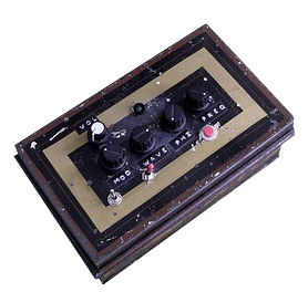
I have been teaching myself some soldering over the last year, to make and augment some musical instruments, and some other, more strange projects. My biggest project by far was this; building a dub siren from scratch. Here I have documented my process and made a guide for anyone who dares to follow in my footsteps.
This dub siren is far from the most simple design. If you want an easy way out, you can find an old birthday card that plays a song or one of those “Mr T in your pocket” gizmos, and just poke’em with a soldering iron and you’re done(like this one). When I started out this project I had no soldering skills at all, but I had some time on my hands and thus I managed to teach myself the basics in a couple of weeks. It was my Christmas holiday, okay? You make it sound like I was unemployed or something.See the full rubdown after the jump.
Breaking news! If you don’t really want your hands wet with all the soldering and hard work, Korg is now releasing their Monotron synth, which does much the same thing as my dub siren, and for the truly nice price of around $85. Product details here. But you don’t want that of course, no, you want to work hard, making your own from scratch! Right? Then read on.
The Dub siren is based around two 555-chips generating the sound. It has buttons for volume, modulation, waveform, phase and frequency. It has a momentary on-button, and also a switch for a «hold» mode. An LED blinks at the waveform rate, and another one to indicate that the hold mode is activated (I skipped that one in my build). Check out the video and schematics at the bottom to see and hear.
Parts needed
IC’s
- LM555n × 2 – I used these, but most 555s will probably do.
- LM741 × 1 – operational amplifier
Pots:
- 50K × 5
Buttons etc.
- off(on) push button × 1 – the momentary on button
- on(on) toggle switch × 1 – permanent on/«hold» switch
- off(on) toggle switch × 2 – modulation on/off switch & power on/off
- LED × 1 – 3mm or 5mm, I used a fiver.
- Either a 9V battery (which will be spent crazy fast), or a 9V wall wart transformer, and a DC socket to plug it in.
- a big TRS socket for the output. You know, like a guitar plug.
- LED holders (for extra finesse and glam)
- IC holders to protect your ICs from overheating when you are soldering. Especially important if your soldering skills are not the best.
- Knobs for the potentiometers
- Some cool casing. I used an old barbers box I found at a flea market.
Capacitors:
- 47μF × 1
- 47nF × 1
- 22μF × 1
- 150nF × 1
- 10μF × 1
Miscellaneous:
- A bunch of resistors. Just buy a packet that has all kinds.
- 2 General purpose NPN transistors (see the circuit diagram below)
If you are Scandinavian and don’t have a store in town that carries the parts, have a look at electrokit.se, where I got (almost) all my parts. Pretty cheap. I later found out Elfa seems to be the industry standard supplier. My experience tells me that buying this stuff online is way cheaper than in a store. And it’s light, so postage is practically free. My 555s I had to order from the UK (totalrobots), so I bought 20 so I’ll never run out.
More things to think about
I actually made this siren twice, the first time around I basically had no idea what I was doing, with the result that if I opened the lid of the siren, or just shook it a little, it would change the sound, or most times just stop working. Hopefully not at a gig. So what to do? Build the whole thing back up from scratch of course!
The second time around I was able to take benefit from everything I had learned from my mistakes. For example, the first version used solid core wiring. Kids, stay away from that stuff! It just breaks all the time. I used it because I was so tired of stripping cables with scissors. Instead, use multi-core wiring and just invest in cable stripper pliers, they are quite cheap.
Secondly, try to make the entire thing on one board, putting all the components as close together as you can. This way you have a way more stable end product, that will not break if you just look at it angrily, like my first one did. As a bonus this makes the whole thing take up less space, enabling you to use a smaller casing. I actually overshot it a bit with my casing, I could easily have gotten away with using something half its size. My tip on this is to wait to decide what to use until after you finished soldering, so you know how much space you need.
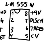
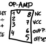
Another thing you need to know about the schematic is; Dave made the IC’s a little confusing. The connection on the top left of your IC does not necessarily correspond with the one on the schematic. I found out what connections are where on the ICs I used (see the pictures above the video). If you use different model IC’s than me you might want to google the model number and go through some PDFs to find it. If you are in doubt, use my drawings to guide you through it.
Another thing is, your line output is going to be huge on this thing. So right before the last output (on the + wire of course), put a resistor, just experiment with different ohms. If not, you might come with the siren to a party, and when some drunken fool rambles up on stage to mash your buttons, he turns the volume all the way up and blows every fuse from here to Calcutta.
According to feedback in the comments, you should tie the 22μF smoothing cap’s negative leg to ground. That way you won’t risk blowing it.
You can nick the original schematic from dave on flickr too. Just keep in mind the alterations I mentioned. If you need to learn how to solder, this article is a good primer.
The schematic is at the bottom of the post, alongside some pictures. Just download that, and see if you can make sense of it. Good luck!
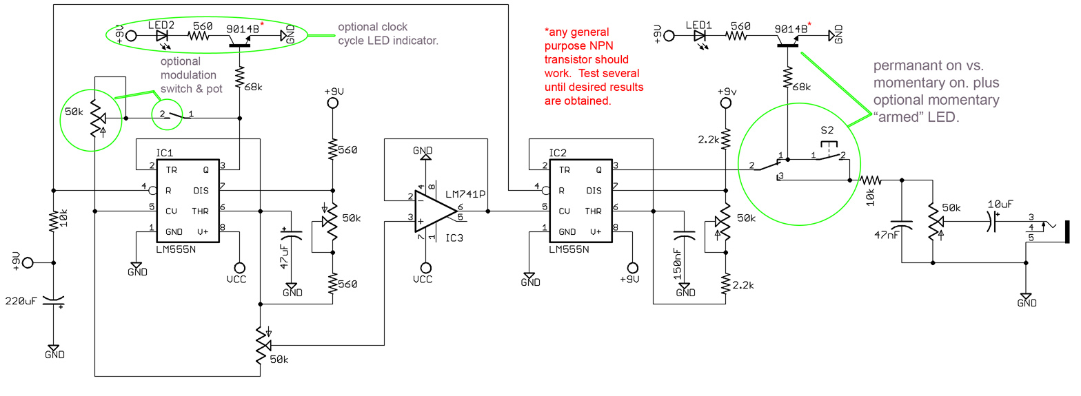
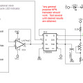
- the main circuit
- the 555 I used
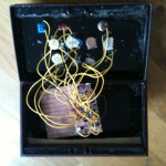
- inside the box (a mess)
- tadaa
- the op-amp I used
that’s about all I can gather from the schematic. Hope I didn’t forget anything. Just holler in the comments if you have questions, or, you know, comments.
UPDATE: This article has gotten a lot of great comments, so I highly recommend reading through them all, as many of them may answer your own questions.
And if you liked this article, how about showing some love on Facebook? If you “like” my page, I’ll let you know about new projects and things you might like. If you are hard-core (as I know you are), you should enlist for my newsletter! mail-outs are fun, rare and full of free stuff.
[et_bloom_inline optin_id=”optin_4″]




Finally finished my build! Having the same problem however as Rob. My siren doesn’t sound bassy at all and is very quiet on the output stage. Also, I have used 2.2K and 560R resistors it tells you to use on each of the two potentiometers, but they do not have much of an effect?? There isn’t much difference in the speed from fully anti clockwise to fully clockwise. This is the same with the pitch. What can I do to increase the ranges these pots run?? I want to be able to have either a dead slow speed or lightning fast, and for the pitch bend either thundering low or ringing high. Any help will be much appreciated. And BS, my parts took a month to arrive, even after selecting the fastest option for postal delivery!
My best bet would be to try pots with different strengths, to fine tune how much stuff happens when you turn them. Also, if the output is weak, change the last resistor to a weaker one. When I built mine, the output was crazy high, so I put in a rather powerful resistor there. Good luck, and show us the results!
Hi Jacob, what resistance pots do you reckon I should try for the pitch and speed, and what resistors should I try for the output volume?? And as a kind of reply to an earlier post, if you tie the negative leg of the 220uF smoothing cap down to ground you have no risk of exploding it, I blew two until I did this! And also, how would I go about uploading a pic to here to show the results?? I’m really pleased with it!
No idea raelly, just try different ones. Try a little math first to get a ballpark feel. Other people in this thread have a lot more knowledge than me on this.
I’ll update the post with the tip about grounding the caps, thanks.
For images, you can try first write a comment, then edit it, and press the IMG button(if that works) Or just write the link to it.
If anybody wouldnt mind doing the maths for me ahem cough cough >D and ill try that and see how it goes.
Couldnt find the edit tab haha but here goes anyway.
//s1258.photobucket.com/albums/ii524/DubSiren2012/?action=view¤t=IMG00183-20120605-1533.jpg#!oZZ2QQcurrentZZhttp%3A%2F%2Fs1258.photobucket.com%2Falbums%2Fii524%2FDubSiren2012%2F%3Faction%3Dview%26current%3DIMG00182-20120605-1532.jpg
two shots show front top and back, with all pots switches leds and connections, really wanna experiment with this thing. Big thanks to Dave on Flickr for the schematics and Jacob for an incredibly informative post!
Comment below what you think.
Those Pots should give you no modulation rate at all( just a normal oscillator, to which you can adjust the frequency on the “pitch pot” ) or top rate from high to low., also the waveform pot affects the modulation on how it goes sinusoidal type or just two tones;
So i dont see why you would want to change it, when it allows you to do that already ! ?!?!
Also, this siren is far from quiet is actually quite pre-amp’ed; so if you connect it to a pre amp, you should bring the volume pot to the minimum values, or else risking blowing your gear as Jacob said and quite well !!
About not being bassy,, i can only say one thing- You have changed the schematic at your own risk !!
Arent you filtering the sound , hence the thin output, i wonder ?!?. Exploding caps would only happen at higher voltages from the top limits. Not on a 220 uF at 9/12 Volts, if it has a 35 V limit value… Sometimes Electrolytic Caps are used inverted due to the same values on ceramic, etc being too expensive in comparison….
Hi BS (& Jacob),
Thanks for your response. There are a couple of things I’d like to mention since the previous poster’s issues (at least a couple of them) are similar to the ones I outlined in my earlier post :
– For me, there’s absolutely no issue with gain on the siren. The signal is nice and hot going into my mixer, but the problem I outlined in my earlier message is to do with the low frequency content of the signal. Even when the note is very low, the note sounds low but there is no LF content present in the signal. There is nothing in my signal chain between the siren and my amplifier, but the effect is that of a high pass filter.
To this end, I’d appreciate it if someone could record a dry sample of their siren with no music or other sound in the background, oscillating between high and low frequencies so I can hear whether mine is the same.
I can’t see in this circuit where the high pass effect can be coming from – the circuit is probably working correctly. But I’d like confirmation from another builder who is happy with their siren that the sound I’m hearing from mine is normal.
– The second thing (and I want to make this clear to ALL builders of this project) is that the 220uF cap polarity IS reversed on the original schematic. I believe, reading earlier posts that Jacob is going to correct this. But! The point of this electrolytic cap in this position in the circuit is as a smoothing cap. It reduces ripple from the PSU when connected correctly with the negative leg tied to ground. There is absolutely no reason in this circuit that the positive leg of this cap should be tied to ground. Connecting the cap the wrong way can, and will, lead to a situation where the cap will pop and explode, and consequently there should be no advice posted on this forum (frequented mostly by newbie electronics DIYers it seems) where advice is given about connecting electrolytic caps with reversed polarity. This is wrong, no to mention potentially dangerous, in almost all circumstances.#
Hope this helps someone.
Cheers
BS, I built the circuit exact to the schematic, apart from the fact I reordered it so that the layout of the IC pins is correct. The siren works fine, it just lacks a bit of low end, like when the siren is running at a low pitch it lacks that oomph. I built this siren not for a hobby but for a dub siren on a reggae sound system. Its got to be a hard working authentic sounding unit, that’s why I built this and not just modded an executor keychain or something like that, I wanted that true authentic sound. And as to the mention of the pots, I wanna be able to run it at a higher or lower frequency than it is at the mo, and I wasn’t talking about the waveform. I’m plentiful happy enough with the swoop of the siren from sine wave to square wave. I was talking about the pot which changes the speed of the siren, or the rate that it osscilates. I want to be able to tweek the siren so that it runs so fast or so slowly that it almost stops being audible. I’m very pleased with the sound its making, its a warm sounding siren and I’d reccommend the build to anybody, its just lacking that low tone that you may get on a slow and low warble, thanks very much for your feedback BS, its clear you are an electronics guy that knows what your on about. Your information and expertise is very useful as I’m no expert, but I wouldn’t say I’m a novice either I’m very familiar with the science of electronics I just didn’t get the maths grades at school I’d need to be able to comprehend the maths involved in it all. And anyway, does it matter if there are novice DIYers?? Its good people want to get involved in it, we all make mistakes every now and again. Otherwise thanks again for your feedback, and big up to Jacob and Dave for brining this info to us all!
well, maybe i explained myself not right, as i didnt want to discourage or attack newcomers to DIY at all, quite the opposite.
Well, i too use it, among many other variations of dub sirens in my studio and with proper nice monitors has oomph to sell and give for free…So, hence the statement that said that dont seem to have any issues with that… Ill test it tomorrow with a Oscilloscope and FFT and let you how low is low in frequency. If possible ill try make a sample recording in the studio gear when possible as well !!
And by the way = Im a reggae dub produce mainly, despite working with other genres as well, professionally, in studio !!
Big up to you BS! Will be in contact soon for some dubplates surely! And its good to hear it, worlds lacking the reggae producers nowadays, keep the tunes flowing, keep the sounds going. And yes the results of the ossciliscope test will be interesting, Ill run a test on mine too and Ill compare results with yours later
Hi,
I’m working on building this unit for my friends. I have a question about the parts.
On the list it mentions a 22µF Capacitor but on the schematic I can only find a 220µF capacitor. Is it an error on the list? Or on the schematic?
Also, I can only find 3 switches on the schematic. Is it so that that actual power on/off switch is omitted in the schematic?
Another question I have is , how much amperage should the 9V adapter be?
Thanks for any help !
Hi Jimmy,
– You need a 220uF electrolytic cap, not 22uF. As per my post above, the polarity on the schematic is incorrect. The negative leg of the cap should be tied to ground.
– There’s no on / off switch on the schematic. Add this yourself if you want it.
– 0.5A or higher will be absolutely fine for your PSU. The current draw for this circuit is much less than that.
Hope this helps…
Rob
Did anyone manage to make a dry sample of their siren by the way?
I’m working on mine this weekend and will record mine then, and as I mentioned I’m unsure about whether the lack of LF on my build is normal or not. If anyone else could make a sample to compare I’d really appreciate it. Daniel…? BS…?
Cheers
Rob
Havent had time, soz… Been quite busy as im finishing other projects at the moment as well- a digital siren with menu, pattern generator, delay and other effects( tyhat will be on second version), LCD displaying all the pot values, and second version of the model will also include midi in for ability to be triggered from DAW… An advanced variation of the ATARI PUNK CONSOLE included in it !! All with the power of a 32 bits uC at @ Mhz !! also Arduino version will be available ( ill eventually post the code and schematics open source style, and shields as well for sale for those who prefer to have it ready to plug in Arduino stylee !).
Here are some final tests of the sounds, etc.. I think only one of them you can see the menu already implemented in the LCD, as it was still in tests stage, soundwise !!
//www.youtube.com/watch?v=vJPU23pHjL0
//www.youtube.com/watch?v=sZovEi63ZeE
//youtu.be/rXVT4Fk3Fjo
That and other version of sirens and delays in DIY Kits for those who prefer to do it with a nice PCB, and have a guide to follow, so they dont get lost( that way even NON knowledgeable people will be able to put up a siren)
But can assure its not normal…its quite nice in low frequencies( dont expect a sub sound though lol) but its more than enough to rattle everything !!
Advice would also be to add a diode ( 1n4001 will do) to protect it from polarity reversal !!. goes between the positive of the PSU and the schematic( negative/line of diode pointing to inside the schematic).
Completed siren #1
I did things a little differently : Big meaty trigger button, inbuilt PSU because I hate wallwarts, inbuilt delay with relay mechanical bypass, LED circle added instead of a single LED to monitor the clock speed (just trigger a 4017 decade counter from pin 3 of IC1. Sounds good and works well…
Pics :
Top view
Side view
Button detail
Corner detail
Engraving detail
Rear view
Apologies – seems that I cocked up two of the links in my previous post. Here they are again :
Button detail
Engraving detail
Wow, awesome! Great work!
Thank you!
And also thanks to you for this project Jacob. This page is a useful resource.
Cheers
Rob
Hi thanks for the links,
a question for the pots, 50k lin or log?
thanks for answer.
cereale
I used 47k linear because none of my normal suppliers had 50k. 47k worked fine.
However, I think that some of the controls may have worked better with a log pot than a Lin. I forget which now, but if you the opportunity I’d get a couple extra log pots along with five Lin pots to experiment.
Hello from Spain!
I have some doubts…
– Is there a similar NPN?
– Is the output TRS jack mono or stereo?
– How is the name of each pots?
Thanks!!
1 : I can’t remember if I used BC549 or 2N3904. I have both around, but any general purpose NPN should work here.
2 : The output of the siren is mono. Pick your connectors accordingly. You could use stereo but it wouldn’t make the siren stereo; it would still be mono.
3 : No one seems to have posted fixed names for the controls. I recommend building the siren and then naming each control to your taste. If you want some inspiration, you can see in the photos I linked above the names I chose.
Cheers
Rob
Blessings to Jacob and Dave for sharing this siren tutorials!
Is there anyone with a pcb scheme (Rob, Jacob?)? Trying to make my own circuit board…
Thanks
A.P.
I made one, but its on a two layer one with vias !! So, not suitable to do at home at all !
I’m working on one too but again it’ll be two layer – not suitable for home etching.
You should be able to create a one sided board for this pretty easily just by drawing out the traces. It isn’t too complicated.
From what i remember when i designed mine, with a couple of jumpers you can design a one layer one, around 7×6 roughly !!
Working the design of a single sided PCB now. Looking like 10 x 5 with not t0o many jumpers, as the leads for the pots & switches negate the need.
Will publish first draft shortly when finished (hopefully next week)
I’ve done some research and I’m working on mine on a program called Eagle.
I’ll let you know about my final result too!
Dont forget to include a good ground plane (Its essential to avoid intereference). caps close to the chips ( specially decoupling ones) and to include a diode at the entrance of the power, to prevent inverted polarity by mistake !!
Im starting to document my AVR and Arduino version of a dub siren which mixes the best of digital and analogue, with LCD, etc… 2nd version, maybe MiDi included as well ( Time allowing).
And the Arduino version will have code ready, so even someone who never touched it can do it !!
Intention is to document it all !
I agree it’s good practice to put the decoupling caps near the IC’s positive & ground leads (even though this is a simple analogue circuit, 555s can behave oddly without a cap between positive & ground). However, on my breadboard the decoupling cap was “miles” from the ICs, yet I could not discern any adverse effects.
Perhaps it might even add to the nuances of the sound!
i’ve made a couple of these, fully working, no problem on output stage also.. BUT
i keep getting this annoying problem.. If i have my permanent switch off, there is still the sound is still leeking to the output.. so I still hear the siren, only much quieter…
Anyone who can help me out with this?
hey ebbin,
i’m having the same problem. anyone has a solution ?
Hi tried this schematic and the other one from interruptor , they are quite similar , in my opinion the second sounds better . The only nice improvement in the second is the position of the switch wich prevents pops when u swich on the effect. I had the same problem of ebbin , it’s due to high output at high frequencies . Solutions : set the siren at a lower volume , or reduce tone frequency pot level , more bassy fix the problem . U can change the two 2,2k resistors with two 4.7k resistors , should fix the problem reducing high frequencies . I suggest not to use the volume more then half way , the output would be too high , u don’t need that much output .
I didn’t tried yet to use the clock led indicator , does it work fine? is it usefull? lookin at the scheme I think the led would be almost always on ?? Am I wrong?
ok Led indicator works , but it lights up in the wrong moment , it lights up when pitch decrease . It should be the opposite , it’s not very usefull like that . They use npn in the scheme but using pnp is better , you can find documentation about “clock cycle 555 led ” , U have to change configuration for the pnp !
I solved the problem of the sound leeking to the output , using shilded wire for pots and for everything (switch, jack-out, power in) . Use a metal enclosure …it’s always a good choice.
About the Leds : One indicates when the momentary button or the permanent switch are on… The other, just as expected from an NPN transistor, lights the led when the voltage that affects the modulation increases( more voltage =more light from the led or no voltage off’s it). So works just as expected…
The noise problem is a design issue… Over amplification, as it was designed for those who dont have access to a pre-amp ( hence being pre-amped…in a cheap way, which includes some noise. Anyone with some basic knowledge can elliminate it, if its that much of a problem ( 5 minutes).
Considering “you can see things” just by looking at the schematic, i thought you would have figured that out ?!
Currently building this for a uni project, got the whole thing built up on a breadboard but I seem to be having a few problems. I’ve used the exact schematic and component values (taking note of the reversed polarity of the soothing cap) but the VCO will not work at all and the rate and mod amount pots on the modulation LFO seem to have dead spots which completely kill the sound past a certain point. I thought that it was due to using trim pots during the testing but the modulation pot works fine, I tested it on an oscilloscope and it modulates between square and saw/sine pretty well.
Can’t seem to get the VCO to work, the only output i’m getting through a guitar amp is clicking, i can change the time between these clicks by changing the mod rate pot (until it reaches dead zone and cuts out) and the volume can be changed.
Any ideas as to what this could be? I’m going into the lab tomorrow to try and remake the VCO timer and see if i can change that but quite concerned with the dead areas on the Mod LFO pots.
Few things… This schematic is already quite amplified … So keep that in mind !
If the posts have dead spots, then something’s wrong ! Check and recheck your wiring, continuity, etc… I know it sounds quite basic, but its where everyone gets stuck, when they do get stuck ! And thats where most people give up as most dont have either the tools or the patience and knowledge ( no matter how basic ) to follow a rational process of elimination… Its always the debugging side of things that puts most people off ! So, without wanting to sound bad, re-check everything again… Until you find your problem ! If not, you made a mistake somewhere ( in the case everything is connected right ). Even if we wanted to help we aint clairvoyants to be able to guess how you have wired things, etc… So usually some detailed pictures might get you somewhere, with any relevant info ! Otherwise is a waste of time to even come asking for help, id say !!Could be anything and everything, and only by the chance of luck we could find the solution this way…
Wishing you the best !!
Thanks a lot for the help, I have my first model built up on a breadboard and it is working pretty well. The problem seemed to be stemming from the ic I used which had been taken from another project, put and brand new one in and away she blew.
As for the dead areas in the pots my suspicion is that it is due to using very cheap low power trim pots on my test unit, hopefully the 1w rated panel mount pots I have ordered will do a much better job.
Good to hear. There is always a siimple explanation. Enjoy it now !! And add delays to it ! lol
The final solution to noise when siren not activated is THIS.
In the schematics they use S2 ( normally open momentary switch ) , this is a very bad choice in signal line . Using Opamp like ua741 or TL071 needs a good design of the circuit to avoid interferences . But if you don’t know how to design it you can use this solution , it works fine .
in the scheme they use :
signal———- (s2 open activated when pressed)—— out
this is not correct , you can use this kind of switching in ligthting lamps but in audio applications this is not recommended.
instead you should use a MOMENTARY NORMALLY CLOSED SWITCH between signal ang ground :
signal——————————————————–
|
NC SWITCH
|
ground ———————————————————-
The nc switch connects the signal to ground when not pressed , and when it ‘s pressed it opens the way to the signal . With this solution you wil not ear interferences when siren is not activated .
NC buttons usually have 3 pins , you use only 2 of them , the central and the NC pin (normally closed), the other is the NO pin (normally open) not to use in this application . You can recognise them using a tester .
I suggest to remove the part on the right regarding the LED when armed and the permanent switch , it’s not very usefull , you can remove the led part , the transistor etc… connect directly 555 pin 3 to 10 k resistor and connect this line with a NC momentary switch to ground.
10k is too low . You can use a 130k resistor or higher value instead if the signal is too strong
If u want an easy solution use a diode in front, before the out// A lazy solution, as the diode has a . voltage drop of around 0.7 V.which in this case gets you close to what you want… Maths from the top of the head .
I modified the schematics correcting errors and simplifing , no transistors , less components , no interferences . tested
//imageshack.us/a/img837/801/modifiedsiren.jpg
This is more clear , inversion polarity protection included with a diod .
You can use a diod 1N4148 .
You can use both 12v dc or 9v dc alimentator .
//imageshack.us/a/img213/801/modifiedsiren.jpg
edited : new easier version !
removed connection beetwen 555 pins 4 , it’s not necessary . Working and tested, less components ,same result ,easier design .
//img685.imageshack.us/img685/4674/modifiedsiren.png
Are you for real ?! Dont get me wrong, but i had to ask !! No disrespect meant !
So you “THINK” you discovered that the pins 4 of the 555 can be left floating ?! Ok, ill explain to you. The pins 4 are held high by an internal 100K resistor… Hence it seems to be working…But good design rules says you should not leave it floating ! Why ?! Stray EMF pulses might reset the chip…
By the way , that was sarcasm, in a way ofjoke ! lol The transistor was theredoing a specific job, and i liked the idea, of it modulating to it. How is your led even working in that ?! Where the ground to it ?! Its not making sense just by looking at it ! But if you say its working, i dont say it isnt… Im just saying it doesnt look right in any way shape or form…
The only problem the circuit had, was quite a high output which can be brought down easy ( you found one of many solutions). The rest, apart from the diode,to protect against invert polarity, doesnt make much sense to me !
Maybe you care to explain me ?!