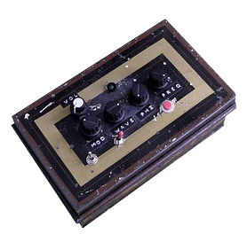
I have been teaching myself some soldering over the last year, to make and augment some musical instruments, and some other, more strange projects. My biggest project by far was this; building a dub siren from scratch. Here I have documented my process and made a guide for anyone who dares to follow in my footsteps.
This dub siren is far from the most simple design. If you want an easy way out, you can find an old birthday card that plays a song or one of those “Mr T in your pocket” gizmos, and just poke’em with a soldering iron and you’re done(like this one). When I started out this project I had no soldering skills at all, but I had some time on my hands and thus I managed to teach myself the basics in a couple of weeks. It was my Christmas holiday, okay? You make it sound like I was unemployed or something.See the full rubdown after the jump.
Breaking news! If you don’t really want your hands wet with all the soldering and hard work, Korg is now releasing their Monotron synth, which does much the same thing as my dub siren, and for the truly nice price of around $85. Product details here. But you don’t want that of course, no, you want to work hard, making your own from scratch! Right? Then read on.
The Dub siren is based around two 555-chips generating the sound. It has buttons for volume, modulation, waveform, phase and frequency. It has a momentary on-button, and also a switch for a «hold» mode. An LED blinks at the waveform rate, and another one to indicate that the hold mode is activated (I skipped that one in my build). Check out the video and schematics at the bottom to see and hear.
Parts needed
IC’s
- LM555n × 2 – I used these, but most 555s will probably do.
- LM741 × 1 – operational amplifier
Pots:
- 50K × 5
Buttons etc.
- off(on) push button × 1 – the momentary on button
- on(on) toggle switch × 1 – permanent on/«hold» switch
- off(on) toggle switch × 2 – modulation on/off switch & power on/off
- LED × 1 – 3mm or 5mm, I used a fiver.
- Either a 9V battery (which will be spent crazy fast), or a 9V wall wart transformer, and a DC socket to plug it in.
- a big TRS socket for the output. You know, like a guitar plug.
- LED holders (for extra finesse and glam)
- IC holders to protect your ICs from overheating when you are soldering. Especially important if your soldering skills are not the best.
- Knobs for the potentiometers
- Some cool casing. I used an old barbers box I found at a flea market.
Capacitors:
- 47μF × 1
- 47nF × 1
- 22μF × 1
- 150nF × 1
- 10μF × 1
Miscellaneous:
- A bunch of resistors. Just buy a packet that has all kinds.
- 2 General purpose NPN transistors (see the circuit diagram below)
If you are Scandinavian and don’t have a store in town that carries the parts, have a look at electrokit.se, where I got (almost) all my parts. Pretty cheap. I later found out Elfa seems to be the industry standard supplier. My experience tells me that buying this stuff online is way cheaper than in a store. And it’s light, so postage is practically free. My 555s I had to order from the UK (totalrobots), so I bought 20 so I’ll never run out.
More things to think about
I actually made this siren twice, the first time around I basically had no idea what I was doing, with the result that if I opened the lid of the siren, or just shook it a little, it would change the sound, or most times just stop working. Hopefully not at a gig. So what to do? Build the whole thing back up from scratch of course!
The second time around I was able to take benefit from everything I had learned from my mistakes. For example, the first version used solid core wiring. Kids, stay away from that stuff! It just breaks all the time. I used it because I was so tired of stripping cables with scissors. Instead, use multi-core wiring and just invest in cable stripper pliers, they are quite cheap.
Secondly, try to make the entire thing on one board, putting all the components as close together as you can. This way you have a way more stable end product, that will not break if you just look at it angrily, like my first one did. As a bonus this makes the whole thing take up less space, enabling you to use a smaller casing. I actually overshot it a bit with my casing, I could easily have gotten away with using something half its size. My tip on this is to wait to decide what to use until after you finished soldering, so you know how much space you need.
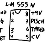
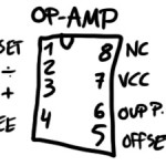
Another thing you need to know about the schematic is; Dave made the IC’s a little confusing. The connection on the top left of your IC does not necessarily correspond with the one on the schematic. I found out what connections are where on the ICs I used (see the pictures above the video). If you use different model IC’s than me you might want to google the model number and go through some PDFs to find it. If you are in doubt, use my drawings to guide you through it.
Another thing is, your line output is going to be huge on this thing. So right before the last output (on the + wire of course), put a resistor, just experiment with different ohms. If not, you might come with the siren to a party, and when some drunken fool rambles up on stage to mash your buttons, he turns the volume all the way up and blows every fuse from here to Calcutta.
According to feedback in the comments, you should tie the 22μF smoothing cap’s negative leg to ground. That way you won’t risk blowing it.
You can nick the original schematic from dave on flickr too. Just keep in mind the alterations I mentioned. If you need to learn how to solder, this article is a good primer.
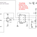
The schematic is at the bottom of the post, alongside some pictures. Just download that, and see if you can make sense of it. Good luck!
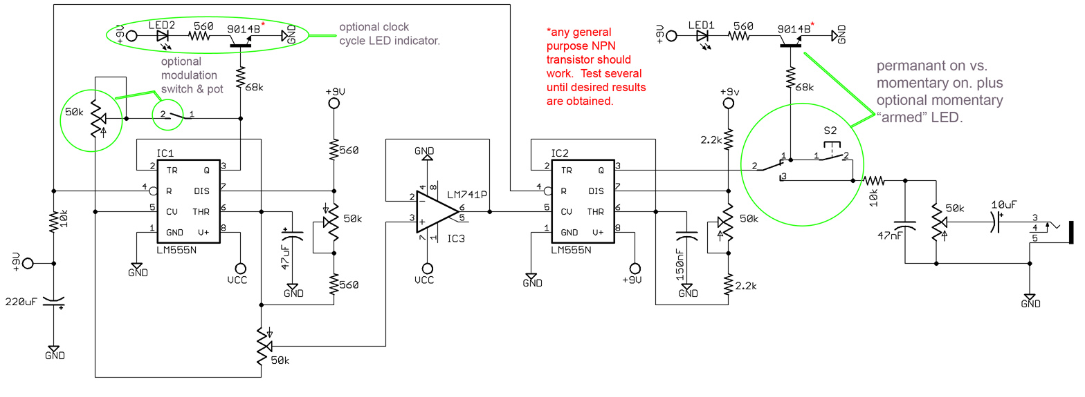
- the main circuit
- the 555 I used
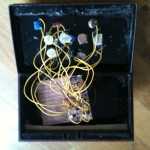
- inside the box (a mess)
- tadaa
- the op-amp I used
that’s about all I can gather from the schematic. Hope I didn’t forget anything. Just holler in the comments if you have questions, or, you know, comments.
UPDATE: This article has gotten a lot of great comments, so I highly recommend reading through them all, as many of them may answer your own questions.
And if you liked this article, how about showing some love on Facebook? If you “like” my page, I’ll let you know about new projects and things you might like. If you are hard-core (as I know you are), you should enlist for my newsletter! mail-outs are fun, rare and full of free stuff.
[et_bloom_inline optin_id=”optin_4″]





Wow, great!
Good work on trying to figure out the arrows… About the LED’s, they have resistors on the other side, so I suppose this should do the trick. Mine works, so… If you wonder if you have blown your LEDs, just put some power straight to them and see if they light up.
Now, about the phaze pot, you might wanna try a pot with a different resistance, or some of the resistance leading up to the pot might be wrong. Experiment with different ohms on the pot and see what works best.
Any and all contributions to my article are appreciated, thanks! I’d be glad to put it in there, if you have some good knowledge to share. And I want pictures of your siren, dude!
Here’s a link to see my siren. Sorry took so long. Respect.
//i25.photobucket.com/albums/c83/stepdubstep/DSCN1379.jpg
Awesome! Congrats!
Nice work mi bredren Stevo.
Since you built one and showed it off now I am going to build one…
thanks for sharing over on the phorum as well…..
HG1
Yo, very nice site and very good descriptions!
I am planning to build one and have studied the schematics bit and simulated with Multisim, but there are a few things I don’t get.. It would be very kind if you have time to help out!
You mention a button for phase, which pot is that?
On the first 555, why do you connect the output (pin 3) to the CV (pin 5)? As I understand it CV is the input you use on the second 555 to change the frequency. I am also confused about the modulation switch and pot.. is it only to mess up the sound?
And the waveform pot I guess is the lower-left one, but that should set the waveform only for the LFO, first 555. Perhaps it would be nice to do something similar on the second 555 to get a square or sawtooth out?
Cheers!
wow, hard questions there. To be honest, I don’t know. I would recommend you just build it, and see what happens. If something doesn’t smell right, you can just change it as you go. But the schematic should be all right as it is, except the positions of the different connections of the 555’s, which change depending on the manufacturer. Sorry!
I have tried making this circuit but all i hear is a clicking sound like a tapping, this has happened with all the sirens i have tried, do you have any suggestions? they would be greatly apreciated as i was really looking forward to having a working siren.
a tapping sound would normally mean that something wrong with your oscillators, but since it’s happened to all your circuits, I reckon your power supply is at fault. But it’s all guesswork, really. Good luck!
Has anyone done a PCB layout that you would like to share? 🙂
Hi !
I have also made your DIY Dub Siren.
Nice Sound ! I liked this.
Here’s a link to see my siren machine.
//www.youtube.com/watch?v=A4tnbmTGIX4
Thank you. Respect.
Wow, awesome Ramen siren, congrats!
Would be nice if someone has a PCB , Point-2-Point or Perfboard layout that can help?
great help man.
i was wondering which resistors did you use,since there are so many kinds…
thanx
The resistance value of each resistor is written in my walkthrough. You can just read up on it on wikipedia or something.
hey man,
i got all the parts and started soldering when i realized my ic’s connections are the same as your drawing (not the same as the schematic…)
does that mean i have to start over and rearrange the connections on the schematic to fit my ic’s or to keep on following the schematic as it is as long as the GND and V are the same as the ones on the schematic?
HELP!! i’m a little lost…
Well, that’s easy. You just rearrange the wires that go into the IC, no need to start over.
Hi man, I finally have my dub siren, it works so good! Thankyou so much for the drawings.. I’ve just one problem, the siren doesn’t work with the echo, I don’t know why, I’m using it without echo now, any suggestion? I have no idea why it doesn’t work..
thanks!
strange. It sounds like there’s something wrong with your echo, really.
You list a 22 uF capacitor, but i’m spotting a little 220 uF in the schematic. Is this a typo?
Hmm, probably a typo, yeah. Trust the schematic over my own list, except where specifically stated, like on the IC’s.
why would like to ask which is the V- direction and where is connected with the battery
Let’s see if I remember it correctly: Both “VCC” and “+9V” are power, while GND are ground, of course. Did that answer your question?
In your last pic, i see what seems two Trs out ?! Am i right ?!? Or is one a dc mains adaptor plug ?! Thanks in advance and thanks for your article on your wicked build !!
Ah, that’s a mains DC plug, yes. And thank you right back!
With all the stress, i managed to do it, Jacob lol Thanks for your patience and time… Just finished a delay to go on same enclosure based on HT8972 IC, though im also bulding another based on the now classic PT 2399… Uoop uoop
220 uF capacitor in bottom left of schematic is reverse polarity! just blew one up was fun.
Its not reversed…And how did you manage to blow one up ?!? Sounds like something really wrong going there ?!?
Make sure you have Capacitors with above values…
Why would you ever connect the positive end on a capacitor to ground and negative end to VCC directly?
Im having trouble finding a 150nf capacitor is there anything that could be used in its place
Not that I know of. Make sure you check on different shops on the web, somebody’s got to have it!
Is this the pure sound of the siren or with reverb. Have built two similar ones but they don´t sound as nice as this one!
Thanks for sharing!!!!
I see now that it´s connected to a reverb and i am curios if it´s possible to use something else than the 555 to get another sound?
If you are referring to the video, the siren is connected to a delay pedal (the one you can see to the left of the siren).
If you want an altogether different sound than what the siren makes, it’s not enough to just change the 555, you have to get into some basic synthesizers. You can find plenty of schematics for that online, and they range from pretty easy to plain impossible to make. Good luck!
There is oather options… U have some music IC’s , purposely built for toys, slarms, etc out there :HK628 ( and some of the whole series HK62x has different ones) UM 3561, and of course a different type of sirens with the CMOS logic chips like 4046,4066…
But what Jacob tried to say is you cant just replace the chips on this circuit… Those are whole different circuits, and most much more complicated.
But, another option is complement this one with other sounds all on same case, 555 is quite good for that actually ! Comes to mind Atari punk console among other noise generators…
But this one jacob has here is one of the best as dub sirens go !!
Thanks Iyah, great answer!
Sweet bless i powered it up but i have alot of feedback static sound and very low volume any suggestions
Also which kind of guitar plug socket should be used sterio or mono thanks
Hey Steve!
If you’re getting feedback and weird noises, it’s probably due to bad soldering, either a shitty connection, or a connection that touches other stuff it shouldn’t.
The guitar plug should be mono.
Good luck!
Hey. Just in the process of building this and am having an incredibly frustrating time. Ive got the circuit breadboarded out but cant get it to work. Can any one clarify that the caps are supposed to be reversed polarity as per the drawings. Also can anyone confirm the output voltages on the 555. Im getting 8volts at the output on chip one and about 1.2volts on chip 2. Does this sound about right? Ive also fitted the optioanl led circuits to the out put on chip one and am getting no light at led. Have tried another transistor on this circuit and also have triewd a second set of chips. Have been over the circuit lots of times checking the wiring to make sure everything is in the right place with no joy. Can anyone help? Cheers Steve K
Hi! Tricky situation. The best bet I can come up with, is that you should check that you are using the right connections on your 555s. Remember, which of the connections that goes to what changes based on what model you use. For example, the one’s I had did not fit the one in the original circuit, so I had to track down the specs online, and have included them in a little drawing at the bottom of the post. Your 555s might be different from that, too.
Other than that, it sounds like you know what you are doing, so all I can do is give you the best of luck. And hope someone else out here might give a better answer? Guys?
Caps polarity definitely correct..
About the transistor, remember that has to be a PNP ( a general one as says on the instructions will do).
Apart from that all i can say is make sure its all correct !!
*NPN
Turns out my soldering was a bit shit on the pots. Have got it up and running now. Still havent got the leds running but will have acrack at that shortly. Thanks for the help and great website. Cheers Steve K
Respect Jacob!! Great post and thanks for the info! Ive built sirens in the past based on the UM3561 and they all sounded pretty lame, been after a schematic for a LM555 siren for a while now, and Ive started building mine as we speak, Ill put a post and pic up as soon as its done!!
Great! Looking forward to see your work =)
Hi again, in the process of building at the moment, the box I’m using is all drilled out and ready, and I’ve just started the circuit and come to a stalemate. I’ve just realised the schematic says a 150nF capacitor and a 47nF, I thought it said the uF equivalent of these! I agree with an earlier post, these are harder to get hold of. I don’t go through any companies like Jameco or Rapid Electronics as my location is very dificult for the postal system to get to and costs a fortune to post. Anybody manage to get hold of packs of a hundred or so of these and can in the kindness of their hearts send me one of each?? Would be very much appreciative as I’m itching to build my siren!!
Hi Daniel! Have you checked places like Elfa? The pieces themselves are so small that postage (even around the world) should be really cheap. Good luck anyways, hope you find the parts!
QUOTE ” … as my location is very difficult for the postal system to get to” …
Don’t get me wrong, but youre contradicting yourself ?!?!?!?
Plus, even the postman was to find you in the end, as you said yourself it costs a fortune to post it .
BS, maybe, all I know is I never get mail that I want, just a huge pile of junk. They just lose all the stuff I want or need.
Just spent the afternoon building this and it works nicely. There are two things though :
How bassy should the siren be when it is playing very low notes? The signal on mine is very hot but it never seems to sound at all bassy – almost like it is being high pass filtereed. I dunno if this is correct or not. Any thoughts anyone?
The other things is that the smoothing cap on the schematic (220uF) is definitely the wrong polarity. If you want to use the smoothing cap, tie the negative leg to ground or you risk the cap exploding.
Cheers
Rob