I have been teaching myself some soldering over the last year, to make and augment some musical instruments, and some other, more strange projects. My biggest project by far was this; building a dub siren from scratch. Here I have documented my process and made a guide for anyone who dares to follow in my footsteps.
This dub siren is far from the most simple design. If you want an easy way out, you can find an old birthday card that plays a song or one of those “Mr T in your pocket” gizmos, and just poke’em with a soldering iron and you’re done(like this one). When I started out this project I had no soldering skills at all, but I had some time on my hands and thus I managed to teach myself the basics in a couple of weeks. It was my Christmas holiday, okay? You make it sound like I was unemployed or something.See the full rubdown after the jump.
Breaking news! If you don’t really want your hands wet with all the soldering and hard work, Korg is now releasing their Monotron synth, which does much the same thing as my dub siren, and for the truly nice price of around $85. Product details here. But you don’t want that of course, no, you want to work hard, making your own from scratch! Right? Then read on.
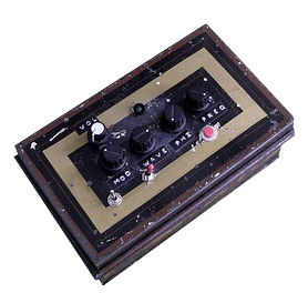
The Dub siren is based around two 555-chips generating the sound. It has buttons for volume, modulation, waveform, phase and frequency. It has a momentary on-button, and also a switch for a «hold» mode. An LED blinks at the waveform rate, and another one to indicate that the hold mode is activated (I skipped that one in my build). Check out the video and schematics at the bottom to see and hear.
Parts needed
IC’s
- LM555n × 2 – I used these, but most 555s will probably do.
- LM741 × 1 – operational amplifier
Pots:
- 50K × 5
Buttons etc.
- off(on) push button × 1 – the momentary on button
- on(on) toggle switch × 1 – permanent on/«hold» switch
- off(on) toggle switch × 2 – modulation on/off switch & power on/off
- LED × 1 – 3mm or 5mm, I used a fiver.
- Either a 9V battery (which will be spent crazy fast), or a 9V wall wart transformer, and a DC socket to plug it in.
- a big TRS socket for the output. You know, like a guitar plug.
- LED holders (for extra finesse and glam)
- IC holders to protect your ICs from overheating when you are soldering. Especially important if your soldering skills are not the best.
- Knobs for the potentiometers
- Some cool casing. I used an old barbers box I found at a flea market.
Capacitors:
- 47μF × 1
- 47nF × 1
- 22μF × 1
- 150nF × 1
- 10μF × 1
Miscellaneous:
- A bunch of resistors. Just buy a packet that has all kinds.
- 2 General purpose NPN transistors (see the circuit diagram below)
If you are Scandinavian and don’t have a store in town that carries the parts, have a look at electrokit.se, where I got (almost) all my parts. Pretty cheap. I later found out Elfa seems to be the industry standard supplier. My experience tells me that buying this stuff online is way cheaper than in a store. And it’s light, so postage is practically free. My 555s I had to order from the UK (totalrobots), so I bought 20 so I’ll never run out.
More things to think about
I actually made this siren twice, the first time around I basically had no idea what I was doing, with the result that if I opened the lid of the siren, or just shook it a little, it would change the sound, or most times just stop working. Hopefully not at a gig. So what to do? Build the whole thing back up from scratch of course!
The second time around I was able to take benefit from everything I had learned from my mistakes. For example, the first version used solid core wiring. Kids, stay away from that stuff! It just breaks all the time. I used it because I was so tired of stripping cables with scissors. Instead, use multi-core wiring and just invest in cable stripper pliers, they are quite cheap.
Secondly, try to make the entire thing on one board, putting all the components as close together as you can. This way you have a way more stable end product, that will not break if you just look at it angrily, like my first one did. As a bonus this makes the whole thing take up less space, enabling you to use a smaller casing. I actually overshot it a bit with my casing, I could easily have gotten away with using something half its size. My tip on this is to wait to decide what to use until after you finished soldering, so you know how much space you need.
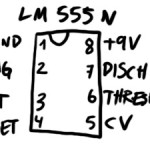
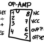
Another thing you need to know about the schematic is; Dave made the IC’s a little confusing. The connection on the top left of your IC does not necessarily correspond with the one on the schematic. I found out what connections are where on the ICs I used (see the pictures above the video). If you use different model IC’s than me you might want to google the model number and go through some PDFs to find it. If you are in doubt, use my drawings to guide you through it.
Another thing is, your line output is going to be huge on this thing. So right before the last output (on the + wire of course), put a resistor, just experiment with different ohms. If not, you might come with the siren to a party, and when some drunken fool rambles up on stage to mash your buttons, he turns the volume all the way up and blows every fuse from here to Calcutta.
According to feedback in the comments, you should tie the 22μF smoothing cap’s negative leg to ground. That way you won’t risk blowing it.
You can nick the original schematic from dave on flickr too. Just keep in mind the alterations I mentioned. If you need to learn how to solder, this article is a good primer.
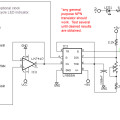
The schematic is at the bottom of the post, alongside some pictures. Just download that, and see if you can make sense of it. Good luck!
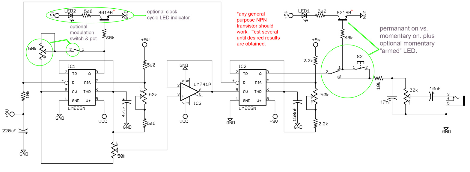
- the main circuit
- the 555 I used
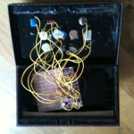
- inside the box (a mess)
- tadaa
- the op-amp I used
that’s about all I can gather from the schematic. Hope I didn’t forget anything. Just holler in the comments if you have questions, or, you know, comments.
UPDATE: This article has gotten a lot of great comments, so I highly recommend reading through them all, as many of them may answer your own questions.
And if you liked this article, how about showing some love on Facebook? If you “like” my page, I’ll let you know about new projects and things you might like. If you are hard-core (as I know you are), you should enlist for my newsletter! mail-outs are fun, rare and full of free stuff.
[et_bloom_inline optin_id=”optin_4″]




very nice…
kool
i from Brazil
dub siren nice
Hey nice work!!! I am going to build on of these and was wondering what does VCC mean in the schematic? Where does this need to be connected?
CHeers!
VCC simply means +9V. Some doofus figured VCC sounded better. Spent some serious time figuring that out myself when i started out!
already bought the parts … I wonder if you used a 9-volt source?
Certainly. Just have a look at the schematic.
Looks awesome man. Great job.
Hey man great job!
I´m from Brzil and i got all the parts to start building my siren i hope it works!
I any case of doubt can i consult u?
Tks
Sure, just holler, and I’ll answer if i can.
hello – nice siren. i’m trying to gather the parts to have one made. i have a few questions. one, are these pots linear or audio taper? and roughly how much did the parts cost you? thanks!
All pots are linear. Everything cost me about 30€. But the price can vary, all the parts are super cheap, but you need lots of parts. I usually buy at least 10 of everything each time.
Hey man me again. tell me this TRS out must be mono or stereo?
Tks
Mono.
hello jacob nice website and briliant job with the siren machine i just wanted to know if a amature like me with no experience could build this in a couple of days
Well. not in a couple of days. The first time it took me about a week, working about two-three hours each day. But I had to learn everything from scratch (although I got some help from dave), if you run into trouble, just ask here.
hi jacob its me again i just wanted to know if you know any uk websites where i could get all the parts from cause i want to give this a go. thanks again
these guys are brilliant: //www.totalrobots.com/
i was about to order the parts but was just wondering what type of capacitors did you use? or does it not really matter? thanks
There’s a list of what level capacitors you need in the middle of the article.
The most important thing is that you get the ones that are hand solder-able. The first time I bought parts, I accidentally got some that were made for soldering by machines, so it was super tiny. It should be explained in the product description, and if there’s an image of it, it looks just like most other parts, a small body with two wires stickin’ out.
where did you get your 50k pots? having a hard time finding any.
Anywhere that you would get other pots, really. 50K is pretty standard. If you can’t find any near you, check out my link to Elfa, in the article.
hello! what kind of capacitors did u use? in ur pics I guess there is one ceramic capacitor right? does it matter if i use electrolyctic capacitors only? thanks
bleesss!
yeah, it should not matter too much I think.
hi man, sorry, but i don’t understand this:
off(on) push button × 1 – the momentary on button > it’s a normally open button
but this? what’s the difference beetween
on(on) toggle switch × 1 – permanent on/«hold» switch
and
<off(on) toggle switch × 2
?
thank you so much
ok, ok, i’ve seen the schematics better.
it’s normally closed.
thankyou
in your siren you haven’t placed the L1 led, right?
the on(on) means a toggle switch with three contacts, so that it can send current either left or right. The off(on) toggle switch is a basic two-pin on/off switch, either sending current or not at all.
You can use a on(on) as a off(on), if you leave the last pin empty. Get it?
ok man, thankyou so much, another question.
the 5 pots, in the schematics, from left to right, what does they means?
1) Modulation
2) …
3) …
4) …
5) Volume
can you explain to me? thnakyou
okay, from left to right:
1: mod
2: rate
3: waveform (square/sine)
4: freq
the knob above the others control volume.
hi man! nice siren!! it has a nice sound so I’m interested in making one for myself!
I found some site that sells electronic parts and they got it ALL, but I do not know about those resistors that you used. what power are they? cause they got them of 1/4w, 1/2w, 1w and 2w (watts) of power! this is a BIG confusion for me because I’m not a proffessional in this!
Okay, then those resistors are bogus, don’t buy them. Resistors come in packets of hundreds, and are measured in ohms. If you can’t find any near you, try to buy them online instead.
Hi!
Congrats for the site/blog!!!!! LOVED IT!!! great video, super groove!! You convinced me to try to build the siren! i have some questions… according to the schematics there should be a 220 uF (electrolitic) and on your list you have 22μF, is it a typo or you really used a 22uF cap?
I saw a post mentioning that the caps can be all eletrolitic but bear in mind that ceramic and eletrolitic are different cap type. (eletrolitic have polarization +- and they “accumulate energy”, ceramic are normaly used to for example filter frequencies.. but then again I am not an engineer 😉 maybe if they are all elect it will still work 😀
To make things easier for the one-go buyer here is a component list that I set together based on your initial post:
IC:
2 x LM555N
1 x LM741
Electrolitic Caps:
1 x 220uF
1 x 47uF
Ceramic Caps:
1 x 10uF
1 x 47nF
1 x 150nF
Resistors (1/4 watt)
2 x 10K
4 x 560 Ohm
2 x 68K
2 x 2.2K
Others:
1 x Female TRS connector (1/4″ 6.35 mm)
1 x 9v battery clip
1 x 2.1mm female DC plug (in case you don’t want to use battery)
2 x 9014B (alternative 2N3904 > not tested)
2 x LED + support casings
2 x SPST switch (ON-OFF)
1 x SPDT switch (ON-ON)
1 x Push-Button (is this one ON by default or OFF by default?!)
1 x Perfurated board for soldering
3 x DIP8 supports for the IC (optional)
Pots:
4 x 50K (linear… I will try a log on volume control)
I will build mine, take pics, and come back with full feedback! i am interested to know tha resistor value to use on the output so the sound volume is not reaaaaaaaaly high 😉
Keep you guys posted,
Cheers
Hey edson, thanks for the great feedback! I suppose it really is a typo then, trust the schematic first, then me.. And for the ceramic/electrolitic caps, I really don’t know. But the whole schematic is supposed to be really flexible, so either might work. Good luck on your siren, and be sure to come back here when you finished it!
Brilliant! I’m gonna have a go at this.
Question-
Edson mentions changing the resistors value to manipulate the total volume. Can the “tone” be manipulated by using different resistor values? Or… which component would I want to focus on if I’m trying to change the tone?
well, the whole box is really “a tone that you can change”…
with frequency and modulation, that’s exactly what you do. But if you want more advanced control, you’ll just run it through a guitar effect box, like I did with a delay pedal in the video.
Please pardon my lack of knowledge when it comes to electronics. Hopefully this project will change that slightly. I collected almost the whole parts list today. I have a few questions.
I count 6 different references on the schematic where it shows +9V. Does that mean everywhere this appears is connected in parallel from the power source?
The VCC is confusing too. I see that the V+ on IC1(555) connects to VCC and the V+ on IC3(555) connects to +9V. Are VCC and +9V synonymous?
Also I see 9 places where the schematic calls for a ground. Should these all be collected together using wiring? And then connect it to the metal enclosure in the end?
Thanks so much for any help!
You are correct in all of your assumptions, all of the points with +9V wants power in parallel. Yes, VCC means power. All the places calling for ground should be hooked up to the ground of the power source, the cord that’s not +9V. Makes sense?
On the far right of the schematic I don’t understand what is going on. Can you explain? Specifically where the #’s 3,4,5 appear there. Thanks!
That’s the 1/4″ jack output, the sound coming from the device. 3, 4&5 is ” Tip, ring and sleeve”, the three connectors on the jack.
Still a bit unclear on the pots. You say the one above is volume, but the highest pot on the schematic is circled in green and referred to as the pot for modulation on the schematic.
So, when you say “above”, do you mean the last pot before the 1/4″ out?
I’ve already started my build. So far, so good. Shouldn’t be long now. I will keep you posted. Thanks!
I mean the top of the enclosure, and thus the last pot before the 1/4″ out, yes. The positioning of the schematic doesn’t have anything to do with how I placed the pots on the box. Good luck!
On the schematic I see 3 switches. Which one is the button trigger(push button)? Is it the one that says S2?
Also since there are only 3 switches shown, does that mean the power switch is left off of the actual schematic? I’m sure I can figure out how to wire it if I need to. Just want to be clear that it’s been left up to the builder since it is dealing only with the power source.
yes, it says “momentary on vs. permanent on”, s2.
and yes. Put a power switch on the + before you split it and send it to all the points on the scematic.
I am working on the output at the moment. I have a ceramic 10uF capacitor to place just before the final +output. However, my capacitor doesn’t appear to show any signs of being polarised. The schematic clearly calls for a polarised cap here. Any thoughts? Do I have the wrong part?
Reading up on capacitors it appears one should normally be using polarised caps above 1uF. Thanks in advance!
Sorry to disappoint you on this one, I have no idea! Caps really aren’t my strongest side.
No worries you have been a great help to me. I will report back if it works well. Some guy on an electronics forum i asked said the unpolarised would work even better. But the ceramics 10-30uF tend to be harder to come by apparently. Almost done!
what do the arrows at the pots mean?
i thought it was the direction the power/electricity flows (don’t know if you say it like that in english), but at the second n555 between discharge and threshold it is otherwise than the first n555?
hope you can help me out with this
No idea, the arrows are probably there just for kicks and giggles for all I know. They have no meaning as far as I can see.
can you eplain to me please for each pot then which pin(1,2,3) goes where/is connected to what? i just don’t get it.. bit stupid ghehe
great that you share this project by the way!
the middle one goes in the middle, and the two other can go either way, it’ll just make the pot go the other way around.. try one way, and switch it if you want it to turn the other way.
The way I understand the arrow is this… From left to right looking at the potentiometer with the 3 connections facing down, the connector on the far left would be first and the far right would be last, using the direction arrow as a guide for which connection on the schematic goes to the first position on the actual pot. I assume this because pots I’ve used on basic equipment(home hifi etc.) turn clockwise minimum to maximum usually. This is only an assumption. You should use google to find countless diagrams and pictures labeled and cross reference them to certain schematics. Just a little bit of investigating online helped me with so much of this project.
Speaking of which, I have completed my siren. And it works! Complicated little buggers they are! First, Jacob… top marks for presenting the schematic and all the info and help. Can’t thank you enough.
Also, my LED’s do not work. Not sure why. I’m scared to take the thing apart again, but I suppose I need to. I have heard that LED’s will short without a resistor inbetween them and the power source. I might try this first.
Also, my phase potentiometer seems to only effect the signal for about an 8th of a whole turn from the beginning of its rotation(from about 7-8 on a clock). Jacob, did your siren do this? I’m wondering if I connected the pot wrong? Could be something else I suppose.
I may come in later with some added help on the parts list(including hidden costs for those with no tools;)). And I will keep an eye to this space to help if I can. Good Luck!